Sunday, August 24, 2014

Infrared, wireless and MSP430


     Couple of years ago, Anaren marketed a radio frequency chip with an integrated antenna working at 900Mhz and based on Code Division Multiple Access Technology (CDMA) technology. Their product was based on Texas Instruments (TI) cc1110 chip and thus TI supported Anaren to market the booster pack board. In addition to anaren RF chip, the booster pack included a board having a prototyping area and a space to place a TI msp430 microcontroller. Off course, Anaren’s booster pack would best work with TI msp430 Launch Pad, see pictures below.
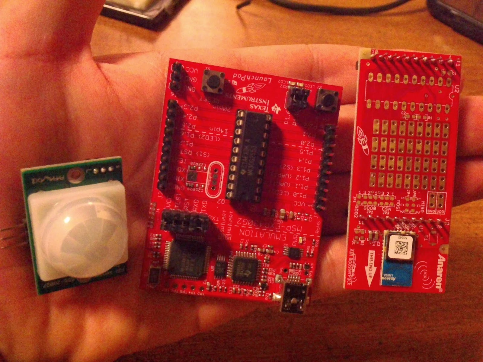
Figure 1 from right to left Anaren booster pack, TI Luanch Pad, and PIR motion detector sensor


     Now, Anaren have their Zigbee chip, Bluetooth chip and finally the celebrated Bluetooth SMART chip. Since their first RF chip (CDMA, 900MHz) was soled at a humble price, and because taking this course helped me to know how to program msp430 ( had to buy and use a TI msp430 lunch pad to do assignments!), I have decided buy one of Anaren booster pack and play around with it. The booster pack has two boards with Anaren RF chips, two microcontrollers pro-flashed with Anaren software stack. Since the later is the most important part in Anaren product, this post will mainly talk about programming the msp430 micro controller to do a certain task involving RF communication. First I had to establish communication between the boards without adding any payload from an external source, this was the easy part. See this link and picture below.


     While experimenting with the booster pack, I needed payload to transmit over the radio frequency link. There were many options including Boolean one/zero, digital data from a sensor, analog data converted by microcontroller to digital data stream. The choices are governed by the fact that booster pack is best used with msp430 launch kit. My choice was a simple one/zero coming from a passive infrared sensor (PIR sensor). You can buy PIR sensor from Radio shack or you can order it from Parallex website. The sensor is made of a basic Pyroelectric sensor and a Fresnel lens covering the sensor; the later is made of a material that pass infrared spectrum between 8-14µm only. Pyroelectric sensor is divided into two half; each half will detect the infrared level on its side as shown below. When both sides reports same levels of infrared they will cancel each other out and no motion is reported. Now parallax claims a field of view (FOV)of 90 degrees; for a explanations of FOV you can see this link (one of my favorite blogs).


Figure 2 Radiated Spectrum with Infrared light wave length marked
 
Picture courtesy of http://electronicsgurukulam.blogspot.com
     

     The programming task of any application involving the booster pack is to allow the micro controller to send and receive data over the radio frequency link and in the same time process data coming from an external source. The normal solution to this problem was to use interrupts.
     Since I had some cool project in mind, the following requirements were already set as the goal of my program:
Upon detecting motion, turn on a led,
As long as motion continues, keep led on,
If motion stops, do not turn led off until a certain time period has elapsed with no motion.

Wednesday, August 20, 2014

Ultrasonic Flaw Detector

     Ultrasound is an important part of Non Destructive Testing techniques; nevertheless theoretical aspect of the ultrasound is still more stressed out when talking about this inspection method. Basic constitutive laws can interrupt the theory behind flaw detector but we will keep this to anther post. This post is more about the practical aspect of flaw detection, one flavor of ultrasound inspection.

      Not the same as flow detection in fluids, flaw detection is concerned with ultrasonic testing of composite materials to find internal discontinuities. This application of the theory of propagation of sound waves through materials has reach long way now and phased array flaw detectors can show sonar like images, like the one we see at doctor clinic. This post is about the standard flaw detector, using a single or a dual element prop to send an ultrasonic waves into materials to detect cracks and irregularities; this is different from thickness detector that reveals only a digit indicating the thickness of the material being inspected.

     Basic Flaw detections devices usually have a screen that display two axis figure, one axis show the distance and the other axis show the amplitude of the reflected signal (measured in dB), please see image below
Figure 1 Ultrasonic Flaw Detector device with echo signal showing on the screen


     Here it is in simple non mathematical terms: When sound wave travels through a medium, at a constant speed, it will disperse in different directions. When hitting an edge of a medium, where the reflection coefficient differs, it will suffer reflection and deflection; the earlier is what we are looking for at our flaw detector screen. Called an echo, this reflection will indicate the nature of the irregularity seen by sound wave as it travels down the medium.

     Now let us talk about how to use the flaw detector, including choosing a prop and analyzing what you see on the screen.

     An angled beam prop, as the name implies, will force the sound wave to travel through the material in angle; thus it is more appropriate to inspect internal discontinuities at some part of a material where we do not have access to surface.

     Straight beam prop is the simplest way to perform an inspection as opposed to using an angled beam prop. Straight beam prop will force the sound wave to travel into the material in straight direction; the sound wave will reflect off any discontinuity it meets on the way. What you see on the screen on the flaw detector is the reflected signal; ideally, you will notice an echo (a peak on the detector screen) at a position (distance) corresponding to the distance of the discontinuity from the surface (where you have placed your prop). In real inspection scenario, you will see a noise floor and you want to look for the first echo reflected back in a series of echo as shown in the picture for the flaw detector screen above. In this picture, you will note the word “GATE” highlighted: it refers to a marker on flaw detector screen that you can move to be placed on the echo signal we just mentioned. Once placed at a position on the screen, marker will display the distance and signal strength received at that position.

Figure 2 Ultrasonic transducer placed on surface of a material with imagery lines showing sound reflecting of a discontinuity 


     Things you need to consider: have you calibrated the flaw detector to account for the propagation delay found in the cable and inside the prop? . You can find some more thoughts on the calibration part in this document. Generally, three methods exist for calibration: depending on the availability of a test block, one can choose to use either Distance, Gain and size curves (DGS), or use a test block with or without Amplitude Distance Correction curve (ADC). Both approaches suffer uncertainties due to ignoring the defect geometry, orientation and surface quality but material attenuation is accounted for in the reference block method.

      While reference block methods are simpler, they can be divided into two categories, one requires the inspector to carry reference blocks to compare defect echo to the reference block echo and the other technique requires establishing ADC curve before inspection. All approaches produce a reading indicating how many dB the defect is larger from the minimum allowable defect size, but in case DGS the Equivalent Reflector Size (ERS) can be obtained form DGS curve directly with some tolerance due to sound attenuation.

     Please stay tuned to know more about constitutive laws the flaw detector use to calculate the distance to a discontinuity in the inspected material; the same laws are used in the ultrasonic range detector to create simple radar!.